
Selecting the correct Wates pressure vessel size based on pump flow is important for reliable booster pump operation. An undersized pressure vessel can cause frequent pump starts and stops, while an appropriately sized vessel helps provide sufficient drawdown, stabilize pressure and reduce unnecessary pump cycling.
Pressure vessel selection should not be based only on the pump motor power or building size. Pump flow rate, start and stop pressure, required minimum pump running time, pre-charge pressure and the type of pump control system should all be considered.
This guide explains the basic principles for selecting a Wates pressure vessel for residential, commercial and industrial booster pump systems.
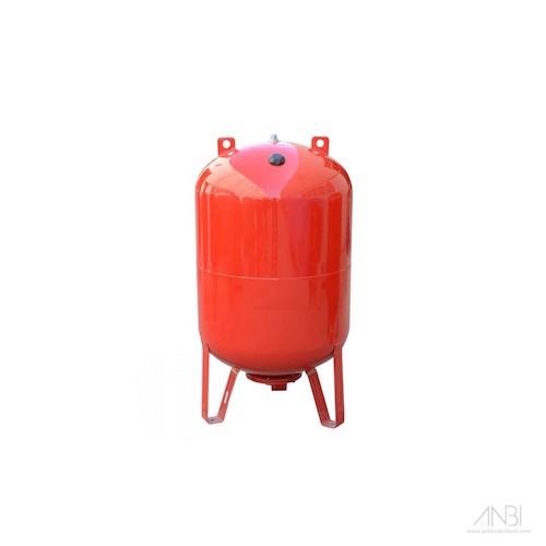
Why Pump Flow Is Important for Pressure Vessel Sizing
Pump flow indicates the quantity of water that a pump can deliver during a given period.
It is commonly expressed as:
- Litres per minute (L/min)
- Litres per second (L/s)
- Cubic metres per hour (m³/h)
A pump with a higher flow rate can require a larger usable vessel drawdown when the system is designed to limit the number of pump starts.
For example:
Pump flow = 6 m³/h
6 m³/h = 6,000 litres/hour
6,000 ÷ 60 = 100 litres/minute
Therefore, the pump delivers approximately 100 litres of water per minute at the stated duty point.
However, this does not mean that a 100-litre pressure vessel should automatically be selected.
The vessel’s nominal capacity and its usable water capacity are different.
What Is Pressure Vessel Drawdown?
Drawdown is the usable quantity of water that leaves the pressure vessel as system pressure falls from the pump stop pressure to the pump start pressure.
For example, a vessel may have a nominal capacity of:
300 litres
but only a portion of this capacity is available as usable drawdown between the selected operating pressures.
The actual drawdown depends mainly on:
- Vessel volume
- Pre-charge pressure
- Pump start pressure
- Pump stop pressure
This is why pressure vessel sizing should be based on required drawdown, rather than nominal vessel capacity alone.
Step 1: Determine the Pump Flow Rate
First, identify the pump flow at the actual operating duty point.
For example:
Pump capacity: 12 m³/h
Convert this into litres per minute:
12,000 ÷ 60 = 200 L/min
Therefore:
Pump flow = 200 litres per minute
Always use the pump flow at the required operating head rather than simply using the maximum flow stated on the pump catalogue.
Step 2: Determine the Required Minimum Pump Run Time
For a conventional fixed-speed booster pump, minimum pump run time is an important consideration.
Assume:
Pump flow = 200 L/min
Required minimum run time = 1 minute
A simplified initial calculation would be:
Required drawdown = Pump Flow × Minimum Run Time
Therefore:
200 L/min × 1 minute = 200 litres
The system would require approximately 200 litres of usable drawdown for this particular design assumption.
The actual required run time and allowable starts per hour should be confirmed with the pump or motor manufacturer’s recommendations.
Step 3: Determine Pump Start and Stop Pressure
Next, identify the pressure settings.
For example:
Pump start pressure = 3 bar
Pump stop pressure = 5 bar
The difference between these two pressures affects the amount of usable water available from the pressure vessel.
Generally, a larger pressure difference can provide greater drawdown from a given vessel, provided all operating conditions remain within the permitted system limits.
Step 4: Determine the Pre-Charge Pressure
Pre-charge is the air pressure inside the vessel before the water side is pressurized.
For many conventional pressure-switch-controlled systems, the vessel pre-charge is set slightly below the pump start pressure, according to the manufacturer’s instructions.
For example:
Pump start pressure = 3.0 bar
A possible pre-charge setting might be:
Pre-charge = 2.8 bar
This is only an example. The correct pre-charge should always follow the vessel and booster pump manufacturer’s recommendations.
Pre-charge should normally be checked with the vessel isolated and the water side completely depressurized.
Step 5: Calculate the Required Vessel Volume
For an idealized diaphragm/bladder vessel calculation, pressures must be converted from gauge pressure to absolute pressure.
A useful theoretical relationship is:
Drawdown fraction = Pₐ × (1/Pstart − 1/Pstop)
where:
Pₐ = absolute pre-charge pressure
Pstart = absolute pump start pressure
Pstop = absolute pump stop pressure
All pressures must use the same absolute-pressure units.
Then:
Required vessel volume = Required drawdown ÷ Drawdown fraction
Example Calculation
Assume:
| Parameter | Value |
|---|---|
| Pump flow | 6 m³/h |
| Pump flow | 100 L/min |
| Required run time | 1 minute |
| Required drawdown | 100 L |
| Pump start pressure | 3 bar gauge |
| Pump stop pressure | 5 bar gauge |
| Pre-charge pressure | 2.8 bar gauge |
For a simplified calculation, adding approximately 1 bar atmospheric pressure gives:
Pre-charge absolute ≈ 3.8 bar
Start pressure absolute ≈ 4.0 bar
Stop pressure absolute ≈ 6.0 bar
Drawdown fraction:
3.8 × (1/4 − 1/6)
≈ 0.317
Therefore:
Required vessel volume = 100 ÷ 0.317
≈ 316 litres
The theoretical minimum nominal vessel volume is therefore approximately 316 litres.
A standard vessel should normally be selected at or above the calculated requirement, subject to the manufacturer’s actual drawdown data and system design.
In this example, a 300-litre vessel would be slightly below the theoretical requirement, so the next suitable standard capacity may need to be considered.
Pump Flow vs Pressure Vessel Size
There is no universal table that can correctly select a pressure vessel based on pump flow alone.
However, the following example illustrates why vessel requirements increase as pump flow increases when the same one-minute run-time and pressure settings are maintained:
| Pump Flow | Flow in L/min | Required Drawdown* | Approx. Theoretical Vessel Volume** |
|---|---|---|---|
| 3 m³/h | 50 | 50 L | 158 L |
| 6 m³/h | 100 | 100 L | 316 L |
| 9 m³/h | 150 | 150 L | 474 L |
| 12 m³/h | 200 | 200 L | 632 L |
| 18 m³/h | 300 | 300 L | 947 L |
| 24 m³/h | 400 | 400 L | 1,263 L |
*Assuming one minute of required drawdown.
**Illustrative calculation assuming approximately 3 bar start pressure, 5 bar stop pressure and 2.8 bar pre-charge. These figures are not a universal Wates sizing chart.
Actual vessel selection should be checked against Wates technical data and the requirements of the pump/control system.
Example: Selecting a Wates Vessel for a 12 m³/h Pump
Consider a fixed-speed booster pump with:
Pump flow: 12 m³/h
Start pressure: 3 bar
Stop pressure: 5 bar
Pre-charge: 2.8 bar
Minimum run-time assumption: 1 minute
Convert the flow:
12 m³/h = 200 L/min
Required drawdown:
200 × 1 = 200 litres
Using the same theoretical drawdown fraction of approximately 0.317:
200 ÷ 0.317 ≈ 631 litres
This means that, under these assumptions, the required nominal vessel volume would be approximately 631 litres.
A standard vessel size above the calculated requirement would then be considered, subject to Wates model availability, actual manufacturer drawdown data and system requirements.
This example also shows why simply selecting a 200-litre vessel for a 200 L/min pump would be incorrect.
What About VFD Booster Pump Systems?
VFD booster pump systems require a different approach.
A Variable Frequency Drive adjusts pump speed according to water demand to maintain relatively constant pressure.
Because the pump does not simply operate between conventional start and stop pressures in the same way as a fixed-speed system, a large drawdown vessel may not be necessary.
A pressure vessel in a VFD system may primarily be used to:
- Handle very small water demands
- Stabilize system pressure
- Reduce unnecessary pump starts
- Absorb transient pressure changes
- Improve controller response
Therefore, do not use the conventional one-minute drawdown calculation automatically for a VFD booster system.
Follow the pump and VFD manufacturer’s recommended vessel sizing method.
Single vs Twin vs Triple Booster Pump Systems
The number of pumps also affects system design.
Single Pump
For a conventional single fixed-speed pump, vessel drawdown can be particularly important for controlling pump cycling.
Twin Pump
A twin-pump booster system may operate with duty/standby or duty/assist logic.
Pressure vessel selection should consider how the controller stages the pumps and the minimum acceptable run time.
Triple Pump
Three-pump systems commonly use staged or variable-speed controls.
Vessel sizing should therefore be coordinated with the complete booster control philosophy rather than simply multiplying vessel capacity by the number of pumps.
Selecting the Correct Pressure Rating
After determining vessel capacity, the required pressure rating must also be checked.
Wates pressure vessels may be available in pressure ratings such as:
10 bar – for systems whose maximum design pressure remains safely within the vessel’s allowable working pressure.
16 bar – for higher-pressure booster and water supply applications.
25 bar – for appropriately designed high-pressure installations.
Do not select the pressure rating based only on normal operating pressure.
Consider:
- Maximum pump shut-off pressure
- Static pressure
- Pump operating pressure
- Possible pressure surges
- System design pressure
- Safety settings
The selected vessel must be appropriately rated for the maximum pressure conditions it may experience.
Common Pressure Vessel Sizing Mistakes
One of the most common mistakes is selecting a vessel based only on pump flow.
Other common errors include:
- Assuming vessel capacity equals usable water capacity
- Ignoring pump start and stop pressures
- Ignoring pre-charge pressure
- Using maximum pump flow instead of duty-point flow
- Ignoring allowable motor starts per hour
- Using fixed-speed sizing calculations for VFD systems
- Selecting an inadequate pressure rating
- Choosing vessel size based only on motor kW
- Selecting according to building height alone
Pressure vessel selection should always consider the complete pumping system.
Information Needed to Select a Wates Pressure Vessel
Before selecting a Wates pressure vessel, collect the following information:
| Parameter | Example |
|---|---|
| Pump flow | 12 m³/h |
| Pump head | 50 m |
| Pump start pressure | 3 bar |
| Pump stop pressure | 5 bar |
| Number of pumps | 2 |
| Pump control | Fixed speed / VFD |
| Minimum run time | Manufacturer requirement |
| Maximum system pressure | Design value |
| Application | Building booster system |
With this information, the required drawdown, nominal vessel capacity and pressure rating can be evaluated more accurately.
Wates Pressure Vessel Supplier in UAE
DXB Solutions LLC supplies Wates pressure vessels for booster pump and water pressure systems in the UAE.
Different vessel capacities and pressure ratings are available for residential, commercial and industrial applications.
Our team can assist with Wates pressure vessel selection based on:
- Pump flow
- Pump head
- Start and stop pressure
- Number of pumps
- Booster pump control method
- Required working pressure
- Application requirements
DXB Solutions LLC serves customers in Dubai, Sharjah, Ajman, Abu Dhabi, Ras Al Khaimah, Fujairah and across the UAE.
Pump flow is an important factor when selecting a Wates pressure vessel, but flow alone cannot determine the correct vessel size.
The correct selection should consider pump flow, required minimum run time, start pressure, stop pressure, pre-charge pressure, control method and maximum system pressure.
For conventional fixed-speed booster systems, calculate the required drawdown first and then determine the nominal pressure vessel capacity capable of providing that drawdown.
For VFD booster systems, follow the specific pump and controller manufacturer’s vessel sizing recommendations.
Correct pressure vessel selection can reduce pump cycling, maintain stable water pressure and support reliable booster pump operation. For more info contact Wates Pressure Vessel Supplier in UAE or call us at +971 4 2522966.