
Low water pressure can make showers, taps and other plumbing fixtures perform poorly, particularly in multi-storey buildings or properties where the incoming water pressure is insufficient. A water booster pump solves this problem by increasing the pressure and helping deliver the required water flow throughout the building.
Booster pump systems are widely used in villas, apartment buildings, hotels, hospitals, schools, commercial properties and industrial facilities across the UAE.
Understanding how a booster pump works can help property owners, contractors and facility managers select the right system for their application.
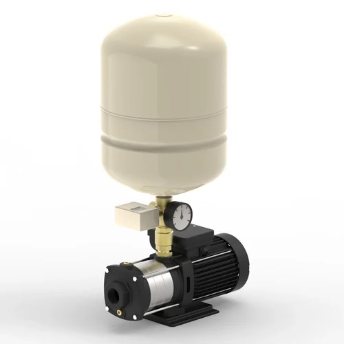
What Is a Water Booster Pump?
A water booster pump is a pump designed to increase the pressure of an existing water supply.
Water may enter the booster system from:
- A ground or underground water tank
- A break tank
- A storage tank
- An existing pressurised water supply
- Another water distribution system
The pump adds energy to the water, increasing its pressure so that it can reach the required outlets at sufficient flow and pressure.
How Does a Booster Pump Work?
A typical booster pump works through a simple process:
Water Source → Booster Pump → Pressure Increase → Distribution Pipework → Water Fixtures
When water demand occurs, system pressure begins to change. The booster pump control system detects this condition and starts or adjusts the pump.
The pump draws water through its suction connection and transfers mechanical energy from the motor to the water.
The pressurised water then enters the building’s distribution network.
When demand decreases, the control system can stop the pump or reduce its speed depending on the type of booster system.
How Does the Pump Increase Water Pressure?
Most building water booster systems use centrifugal pumps.
Inside the pump is a rotating component called an impeller.
When the electric motor rotates the impeller:
- Water enters the pump through the suction connection.
- Water enters the impeller.
- The rotating impeller transfers energy to the water.
- Water moves through the pump casing or diffuser stages.
- This energy is converted into useful pressure and flow.
- Pressurised water leaves through the discharge connection.
The amount of pressure generated depends on the pump design, impeller diameter, number of stages, rotational speed and operating flow.
Why Are Multistage Pumps Commonly Used for Booster Systems?
Many water booster systems use vertical multistage centrifugal pumps.
Instead of using only one impeller, a multistage pump contains several impellers arranged in series.
Each stage increases the water’s energy further.
For example:
Stage 1 → Pressure increases
Stage 2 → Pressure increases further
Stage 3 → Additional pressure
Stage 4 → Higher final discharge pressure
This makes multistage pumps particularly suitable for applications requiring relatively high pressure with a compact pump design.
They are commonly used for:
- Building water supply
- High-rise applications
- Hotels
- Commercial buildings
- Industrial water systems
- Pressure boosting
What Happens When You Open a Tap?
Consider a VFD-controlled booster pump system.
When all taps are closed, there is little or no water demand and the system maintains its target pressure.
Suppose the target pressure is:
4 bar
When someone opens a tap:
Step 1: Water begins flowing from the system.
Step 2: System pressure tends to decrease.
Step 3: A pressure sensor detects the change.
Step 4: The controller commands the booster pump to operate or increase speed.
Step 5: The pump supplies additional water and pressure.
Step 6: The control system continuously adjusts operation to maintain approximately the required pressure.
When the tap is closed, demand decreases. The controller reduces pump speed and, where appropriate, eventually stops the pump.
Fixed-Speed Booster Pump Operation
A traditional fixed-speed booster pump generally operates at its rated motor speed when running.
A pressure switch or controller can be used to start and stop the pump according to predetermined pressure settings.
For example:
Pump starts: when pressure falls to the configured start point.
Pump stops: after demand ends and the system reaches the required stop condition.
Fixed-speed systems can be simple and effective for applications where water demand is relatively predictable.
However, where demand varies substantially, variable-speed control may provide smoother pressure regulation.
How Does a VFD Booster Pump Work?
A Variable Frequency Drive (VFD) controls the speed of the electric motor.
Instead of simply switching the pump fully ON or OFF, the VFD can increase or decrease motor speed according to demand.
A pressure sensor continuously measures discharge pressure.
Suppose the system is set to maintain:
4.5 bar
If pressure falls below the target as demand increases, the controller increases pump speed.
When demand decreases, the pump slows down.
This allows the system to maintain relatively constant water pressure while adapting to changing consumption.
Benefits of VFD Booster Pumps
VFD-controlled systems can provide:
- More consistent water pressure
- Reduced pressure fluctuations
- Improved control
- Reduced unnecessary pump operation
- Potential energy savings
- Smoother starting
- Better response to variable water demand
They are particularly useful in apartment buildings, hotels and commercial properties where demand changes throughout the day.
How Does a Twin Booster Pump System Work?
Larger applications may use two pumps.
A typical arrangement could be:
Duty + Standby
Pump 1 operates as the duty pump.
Pump 2 remains available as standby.
The controller can alternate the duty pump periodically to distribute operating hours.
If one pump develops a fault, the standby pump can provide backup, depending on the system design.
Duty + Assist
When demand is low, one pump operates.
When demand increases beyond the capacity of the first pump, the second pump starts and assists.
This provides additional flow during peak consumption.
How Does a Three-Pump Booster Set Work?
Larger residential and commercial buildings may use three or more pumps.
For example:
Pump 1 – Duty
Pump 2 – Assist
Pump 3 – Standby
At low demand, only one pump may operate.
As water demand increases, the controller can start the second pump.
If additional redundancy is required, the third pump can remain available as standby.
The exact operating philosophy depends on the booster system design and control programming.
What Does a Pressure Vessel Do?
A pressure vessel is commonly installed on the discharge side of a booster system.
Inside the vessel is typically a flexible diaphragm or bladder separating water from a pre-charged air cushion.
The pressure vessel can help:
- Reduce frequent pump starts
- Stabilise system pressure
- Absorb pressure fluctuations
- Supply a small amount of water during minor demand
- Reduce unnecessary pump cycling
The vessel should be correctly sized and pre-charged according to the booster system’s operating requirements.
Main Components of a Booster Pump System
A complete booster set may contain:
Booster Pumps – generate the required flow and pressure.
Electric Motors – provide mechanical power to the pumps.
VFDs – regulate motor speed where variable-speed control is used.
Pressure Sensor – continuously measures system pressure.
Pressure Vessel – helps stabilise pressure and reduce cycling.
Control Panel – manages pump operation, sequencing and protection.
Suction Manifold – distributes incoming water between multiple pumps.
Discharge Manifold – collects pressurised water from the pumps.
Non-Return Valves – prevent reverse water flow.
Isolation Valves – allow individual pumps or components to be isolated for maintenance.
How Does a Booster Pump Maintain Constant Pressure?
Consider a three-pump VFD booster set with a target pressure of 5 bar.
During low demand:
Pump 1 → Runs at reduced speed → Maintains 5 bar
As demand increases:
Pump 1 → Speeds up → Maintains 5 bar
If demand becomes greater than Pump 1 can efficiently handle:
Pump 1 + Pump 2 → Operate together → Maintain required pressure
When demand falls:
Pump 2 → Stops
Pump 1 → Reduces speed
When demand becomes negligible:
Pump → Stops when permitted by the control logic
This automatic adjustment allows the booster set to respond to varying water consumption.
Flow and Pressure in a Booster Pump
Understanding the difference between flow and pressure is essential.
Flow
Flow represents the quantity of water delivered.
For example:
20 m³/h
Pressure
Pressure represents the force available to move the water through the system.
For example:
5 bar
A booster pump must satisfy both requirements simultaneously.
Therefore, the correct way to specify a pump is through a duty point such as:
20 m³/h @ 50 metres head
rather than simply requesting a “5 bar booster pump.”
Where Are Water Booster Pumps Used?
Water booster pump systems are commonly installed in:
- Villas
- Residential buildings
- High-rise towers
- Hotels and resorts
- Hospitals
- Schools and universities
- Shopping malls
- Office buildings
- Warehouses
- Industrial facilities
- Irrigation systems
The required pump configuration varies considerably depending on the application.
Why Does a Building Need a Booster Pump?
A booster system may be required because of:
Insufficient Incoming Pressure
The available water pressure may not be sufficient for the building.
Building Height
Water must be pumped upward to reach upper floors.
High Water Demand
Several fixtures operating simultaneously can increase the required flow.
Pressure Loss
Long pipe runs, valves, fittings and other components create friction losses.
Water Tank Supply
Buildings supplied from ground-level or underground tanks require pumps to distribute water throughout the property.
Example of Booster Pump Operation
Consider a building requiring:
Flow: 20 m³/h
Required Head: 50 metres
The selected booster system should be capable of producing approximately:
20 m³/h @ 50 m head
During periods of low demand, the building may require only 5 m³/h.
A VFD system can reduce pump speed accordingly.
During peak demand, the system may approach 20 m³/h, requiring increased pump speed or operation of additional pumps.
This is why variable-speed multi-pump systems can be effective for buildings with fluctuating water consumption.
Conclusion
A water booster pump works by adding energy to the water to increase its pressure and deliver the required flow throughout a building.
When water demand increases, the booster system responds by starting a pump, increasing pump speed or bringing additional pumps into operation. When demand decreases, the system reduces output accordingly.
Modern VFD booster systems combine pumps, pressure sensors, pressure vessels and automatic controls to maintain stable water pressure while adapting to changing demand.
Correct booster pump selection should always consider flow rate, total head, available inlet pressure, building height and operating conditions.
For residential, commercial and industrial projects, working with experienced booster pump suppliers in UAE can help ensure that the pump and control system are properly matched to the application’s hydraulic requirements. For more info contact Booster Pump Suppliers in UAE or call us at +971 4 2522966.