
Calculating Total Dynamic Head (TDH) is one of the most important steps when selecting a water pump for residential, commercial and industrial applications.
Whether designing a water booster pump system for a high-rise building, selecting an end suction pump for chilled water circulation or installing a water transfer pump for a storage tank, understanding total dynamic head helps ensure the pump delivers the required flow and pressure.
Incorrect head calculations can result in insufficient water pressure, excessive energy consumption, pump oversizing and premature equipment failure.
In this guide, DXB Solutions LLC, a water pump supplier in Dubai, explains what total dynamic head is, how to calculate it, the main components involved and practical examples for different pumping applications.
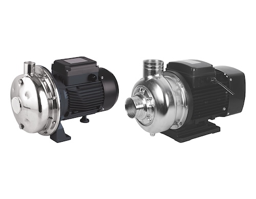
1. What Is Total Dynamic Head (TDH)?
Total Dynamic Head is the difference in total hydraulic head between the discharge and suction sides of a pump at a particular operating flow rate.
It represents the amount of hydraulic energy per unit weight that the pump must add to the water to overcome the system requirements.
TDH is normally expressed in metres (m) or feet (ft).
The required TDH depends on several factors, including:
- Elevation difference between the source and delivery point
- Pressure difference between suction and discharge
- Friction losses through pipelines
- Resistance from valves, elbows and fittings
- Changes in fluid velocity
For accurate pump selection, TDH must be calculated at the required operating flow rate.
2. Total Dynamic Head Formula
For a pumping system between two reference points, the general energy equation can be written as:
TDH = (P₂ − P₁)/(ρg) + (Z₂ − Z₁) + (V₂² − V₁²)/(2g) + Hf
Where:
- P₁ = Pressure at the inlet reference point (Pa)
- P₂ = Pressure at the outlet reference point (Pa)
- ρ = Liquid density (kg/m³)
- g = Gravitational acceleration (9.81 m/s²)
- Z₁, Z₂ = Elevation of the reference points (m)
- V₁, V₂ = Average liquid velocity at the reference points (m/s)
- Hf = Total head losses between the reference points (m)
The equation assumes steady, incompressible flow, with no other pump or turbine between the selected reference points.
For many simplified open-tank water transfer applications, where both liquid surfaces are exposed to atmospheric pressure and surface velocities are negligible:
TDH = Static Elevation Head + Pipe Friction Losses + Fitting Losses
For systems requiring additional outlet pressure, the required pressure head must also be included.
3. Understanding the Main Components of TDH
Static Head
Static head represents the elevation difference between the relevant source and delivery reference points.
For example, if water is pumped from an open ground-level tank to an open tank 30 metres higher, the static elevation head is 30 metres.
Pressure Head
Pressure head represents the energy associated with the pressure difference between the selected inlet and outlet reference points.
For water at typical temperatures:
1 bar ≈ 10.2 metres of water head
If the delivery point requires 2 bar gauge pressure and the source is an atmospheric tank, approximately 20.4 metres of pressure head must be included.
Friction Head
Friction head represents energy losses caused by water flowing through pipes.
It depends on:
- Flow rate
- Pipe length
- Internal pipe diameter
- Pipe material and roughness
- Water velocity
- Liquid properties
Minor Losses
Minor losses are caused by components such as:
- Elbows
- Tees
- Valves
- Strainers
- Check valves
- Reducers and fittings
Despite the name, minor losses can become significant in systems with numerous fittings or high flow velocities.
4. Step-by-Step Total Dynamic Head Calculation
Consider a water transfer system supplying an elevated outlet from an atmospheric ground-level storage tank.
The design conditions are:
| Parameter | Value |
|---|---|
| Required flow rate | 20 m³/h |
| Static elevation difference | 25 m |
| Required outlet pressure | 2 bar gauge |
| Pipe friction losses | 8 m |
| Fitting and valve losses | 3 m |
Step 1: Calculate Static Head
Static elevation head = 25 m
Step 2: Convert Pressure Into Head
Pressure head = Pressure × 10.2
2 × 10.2 = 20.4 m
Step 3: Calculate Total Friction Losses
Pipe friction losses = 8 m
Fitting and valve losses = 3 m
Total losses = 11 m
Step 4: Calculate TDH
TDH = 25 + 20.4 + 8 + 3
Total Dynamic Head = 56.4 metres
The pump should therefore be selected to deliver approximately:
20 m³/h at 56.4 metres head
This simplified example assumes negligible velocity-head difference between the reference points. The actual selection must be verified using the manufacturer’s pump performance curve.
5. How to Calculate Pipe Friction Losses
Pipe friction losses can be calculated using the Darcy-Weisbach equation:
Hf = f × (L/D) × (V²/2g)
Where:
- Hf = Friction head loss (m)
- f = Darcy friction factor
- L = Pipe length (m)
- D = Internal pipe diameter (m)
- V = Average water velocity (m/s)
- g = Gravitational acceleration (9.81 m/s²)
The Darcy friction factor depends on Reynolds number and relative pipe roughness.
Example
Consider the following pipe conditions:
- Pipe length = 100 m
- Internal pipe diameter = 0.08 m
- Water velocity = 1.5 m/s
- Assumed Darcy friction factor = 0.02
Friction loss:
Hf = 0.02 × (100/0.08) × (1.5² / 19.62)
Hf ≈ 2.87 metres
This represents the straight-pipe friction loss for the assumed conditions. Losses from valves, elbows and other fittings must be calculated separately.
6. How to Calculate Losses Through Valves and Fittings
Valves, elbows and other fittings create additional resistance to water flow.
A common method for calculating these losses is:
Hm = K × V² / 2g
Where:
- Hm = Head loss through the fitting (m)
- K = Fitting loss coefficient
- V = Water velocity (m/s)
- g = Gravitational acceleration (m/s²)
Example
Assume the total loss coefficient of all fittings is 8 and the water velocity is 1.5 m/s.
Hm = 8 × 1.5² / 19.62
Hm ≈ 0.92 metres
The fitting loss coefficients should be obtained from appropriate engineering references or manufacturer data.
7. Total Dynamic Head Calculation for a Booster Pump System
Booster pumps are commonly used in villas, apartment buildings, hotels and commercial properties throughout Dubai.
Consider a simplified booster pump installation with the following conditions:
- Static elevation difference = 35 m
- Required pressure at the highest outlet = 2 bar
- Pipe friction losses = 7 m
- Additional fitting losses = 3 m
- Source tank open to atmosphere
Required pressure head:
2 × 10.2 = 20.4 m
Total dynamic head:
TDH = 35 + 20.4 + 7 + 3
TDH = 65.4 metres
The pump must deliver the design flow at approximately 65.4 metres head under these assumptions.
For a booster system supplied from a pressurized inlet, the available inlet pressure must be accounted for rather than assuming atmospheric pressure.
8. Total Dynamic Head Calculation for Chilled Water Pumps
Chilled water pumps are widely used in HVAC systems in Dubai and across the UAE.
Unlike open water transfer systems, a completely filled closed-loop chilled water circuit does not normally require the circulation pump to overcome the full building height.
The static elevation gains and losses cancel around the closed circuit.
Therefore, for a typical closed-loop system:
Required Pump Head ≈ Total Circuit Friction and Equipment Losses
These losses may include:
- Supply and return piping
- Chillers and heat exchangers
- Cooling coils
- Control valves
- Strainers and balancing valves
- Other system components
Example
| Component | Head Loss |
|---|---|
| Supply and return pipes | 8 m |
| Chiller or heat exchanger | 5 m |
| Cooling coils | 4 m |
| Control and balancing valves | 3 m |
| Fittings and strainers | 2 m |
| Total | 22 m |
The required pump head is approximately 22 metres at the design flow rate.
This assumes a fully filled closed circuit with appropriate pressurization and no additional elevation or pressure requirements between the selected reference points.
9. Total Dynamic Head Calculation for Submersible Pumps
Submersible pumps are commonly used for borewell water supply, drainage, sewage and construction dewatering.
For a borewell pump, the TDH calculation may include:
- Vertical difference from pumping water level to delivery point
- Required delivery pressure
- Rising main friction losses
- Fitting and valve losses
Example
Consider a borewell installation with:
- Pumping water level = 40 m below ground
- Delivery point = 10 m above ground
- Required outlet pressure = 1.5 bar gauge
- Pipe and fitting losses = 8 m
Static elevation difference:
40 + 10 = 50 m
Pressure head:
1.5 × 10.2 = 15.3 m
Total dynamic head:
TDH = 50 + 15.3 + 8
TDH = 73.3 metres
The pump should be selected to deliver the required flow at approximately 73.3 metres head.
The dynamic pumping water level should be used rather than only the static water level, because the level can drop during pumping.
10. Relationship Between Flow Rate and Total Dynamic Head
For most water piping systems, friction losses increase as flow rate increases.
This means the required TDH may also increase with flow.
For example:
| Flow Rate | Illustrative System Head |
|---|---|
| 5 m³/h | 30 m |
| 10 m³/h | 33 m |
| 15 m³/h | 38 m |
| 20 m³/h | 45 m |
| 25 m³/h | 54 m |
These are illustrative values for a hypothetical system.
The actual operating point is determined by the intersection of the pump performance curve and the system head curve.
11. Common Mistakes in Total Dynamic Head Calculation
Ignoring Pipe Friction Losses
Long pipelines and undersized pipes can create significant head losses.
Confusing Pump Head With Building Height
The required head includes pressure and friction requirements, not just elevation.
Adding Building Height in a Closed HVAC Circuit
For a completely filled closed chilled water circuit, static elevation normally cancels and should not be added as a circulation head requirement.
Ignoring Available Suction Pressure
Positive inlet pressure can reduce the additional head required from a booster pump.
Using Maximum Pump Head as the Duty Point
A pump’s maximum head usually occurs near zero flow and should not be confused with its head at the required design flow.
Applying Arbitrary Safety Margins
Excessive allowances can lead to oversized pumps, higher energy consumption and control problems. Design allowances should be justified.
12. How to Select a Water Pump Using TDH
After calculating total dynamic head, follow these steps:
- Determine the required flow rate.
- Calculate TDH at the design flow.
- Identify a suitable pump type.
- Review manufacturer flow-versus-head performance curves.
- Confirm that the operating point falls within the recommended range.
- Check pump efficiency and motor absorbed power.
- Verify NPSH available against the pump’s NPSH requirements.
- Review installation conditions, materials and electrical requirements.
For critical installations, consider duty-and-standby arrangements or multiple-pump systems where appropriate.
13. Water Pump Suppliers in Dubai – DXB Solutions LLC
DXB Solutions LLC supplies water pumps and pumping solutions for residential, commercial and industrial applications throughout Dubai and the UAE.
Our product range includes:
- End suction centrifugal pumps
- Vertical multistage pumps
- Horizontal multistage pumps
- Water booster pump systems
- Submersible drainage and sewage pumps
- Borewell pumps
- HVAC circulation pumps
- Industrial water pumps
We work with established pump manufacturers, including Ebara, Grundfos, Lowara, Goulds, Pedrollo, Tsurumi and Wilo.
Our team can assist customers with pump enquiries, flow and head calculations, technical selection and identifying suitable equipment for different applications.
Understanding how to calculate total dynamic head for water pumps is essential for correct pump selection and reliable system operation.
TDH calculations account for elevation differences, pressure requirements and hydraulic losses throughout the system.
Correct calculations help avoid undersized or oversized pumps, reduce energy consumption and improve long-term reliability.
For residential, commercial and industrial water pump applications in Dubai and across the UAE, DXB Solutions LLC supplies a wide range of pumping equipment. For more info contact Water Pump Suppliers in Dubai or call us at +971 4 2522966.